L3 Project
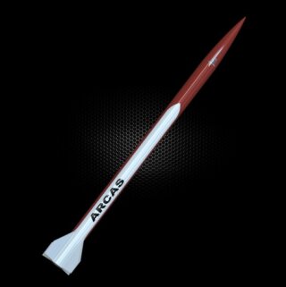
Table of Contents
- L3 Project
- Flight and Results
Introduction
The L3 certification is the highest level of certification that the NAR offers, and it allows a flyer to fly M-O impulse motors. For my L3 project, I will fly a full-scale HV Arcas on an AeroTech M650W to an estimated altitute of 14,000 ft. The Arcas is 4.5” in diameter, 7.5 ft tall, weighs 30.3 lbs (with motor) and is configured with a 75mm motor mount tube. This rocket is a 1:1 full-scale model of the Arcas sounding rocket
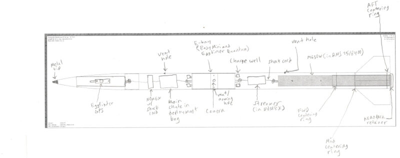
The Arcas has redundant dual-deployment flight computers (altimeters). The primary flight computer is the Altus Metrum EasyMini, which deploys the drogue at apogee and the main parachute at 1000ft AGL. The secondary flight computer is the Eggtimer Quantum, which fires an ejection charge for the drogue at apogee + 2 seconds and fires an ejection charge for the main at 800ft AGL.
In addition to the two flight computers described above, the Arcas will have a Raspberry Pi Zero W with an accelerometer, bme280 pressure/temperature sensor, and camera. This computer is “optional” and will have no control over the flight. This eliminates any risk to the flight. It was added since the purpose of the original Arcas was to gather weather data. It is also used to assist in the ground testing of the EasyMini.
I’d like to thank my rocketry mentor, Jim Horstrup, and my L3CC, John Lyngdal, for all of their help and advice with this project. Thanks to John Thompson for coming down to Brothers to witness the flight as an L3CC. Additionally, I’d like to thank Brie Hall for 3D printing the fin alignment guide and for all of her advice on materials, epoxies, and building of fiberglass rockets. Finally, I’d like to thank Scott Hewitt (my father) for his “tools, parts, help, and advice” with this project!
Diagram
Construction
Components
The major components of the Arcas are as follows:
- Nose Cone: Filament Wound 4:1 Von Karman with Metal Tip
- Airframe (booster): G12 Fiberglass (48” long)
- Airframe (payload bay): G12 Fiberglass (24” long)
- E-bay: G12 Fiberglass Coupler (12” long)
- E-bay lids: G10 Fiberglass (2 count)
- Motor mount: G12 Fiberglass (16” long)
- Centering Rings: G10 fiberglass (3 count)
- Fins: G10 Fiberglass (3/16” thick; 4 count)
- Rail buttons: 1515 Delrin with flange nut on the back
Adhesives
- West System 105/205 Epoxy
- West System 105/207 (special clear) for fin fiberglassing
- West System 742 Fiberglass Fabric for fin fiberglassing
- J-B Weld for motor retainer and other areas where extra strength is needed.
Steps
See below for the figures referenced.
The Arcas was constructed as follows:
- The motor tube and centering rings were sanded with 60-grit sandpaper to allow adhesion of the epoxy.
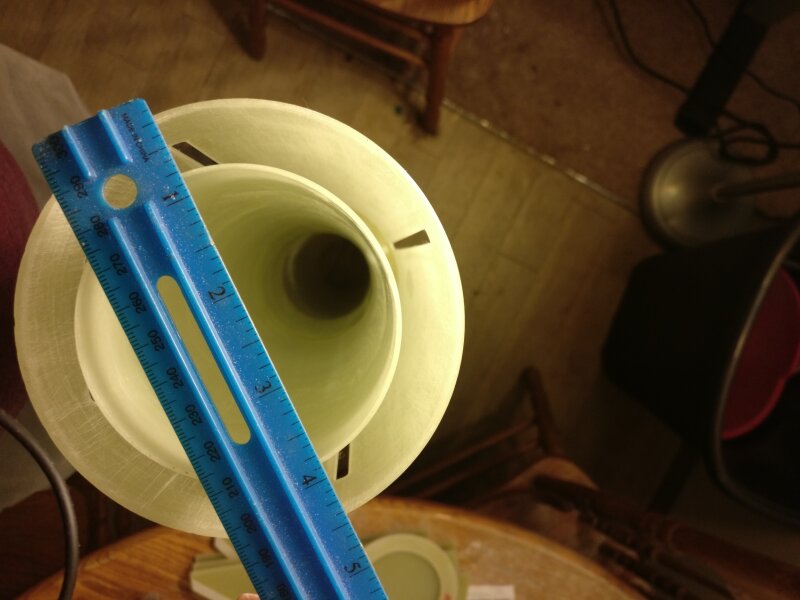
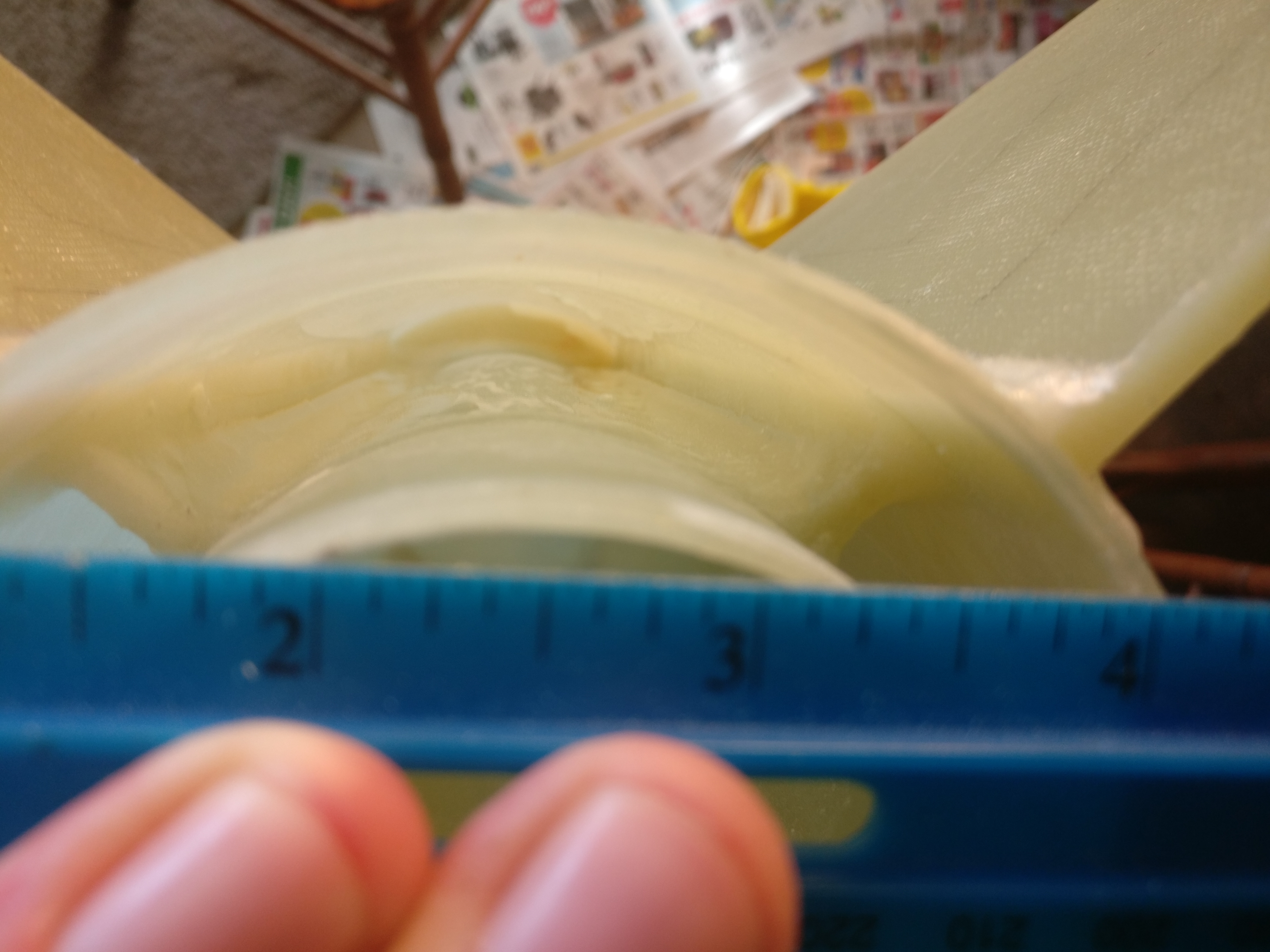
- The forward centering ring was epoxyed 1/2” from the end of the motor tube. (Figure 2)
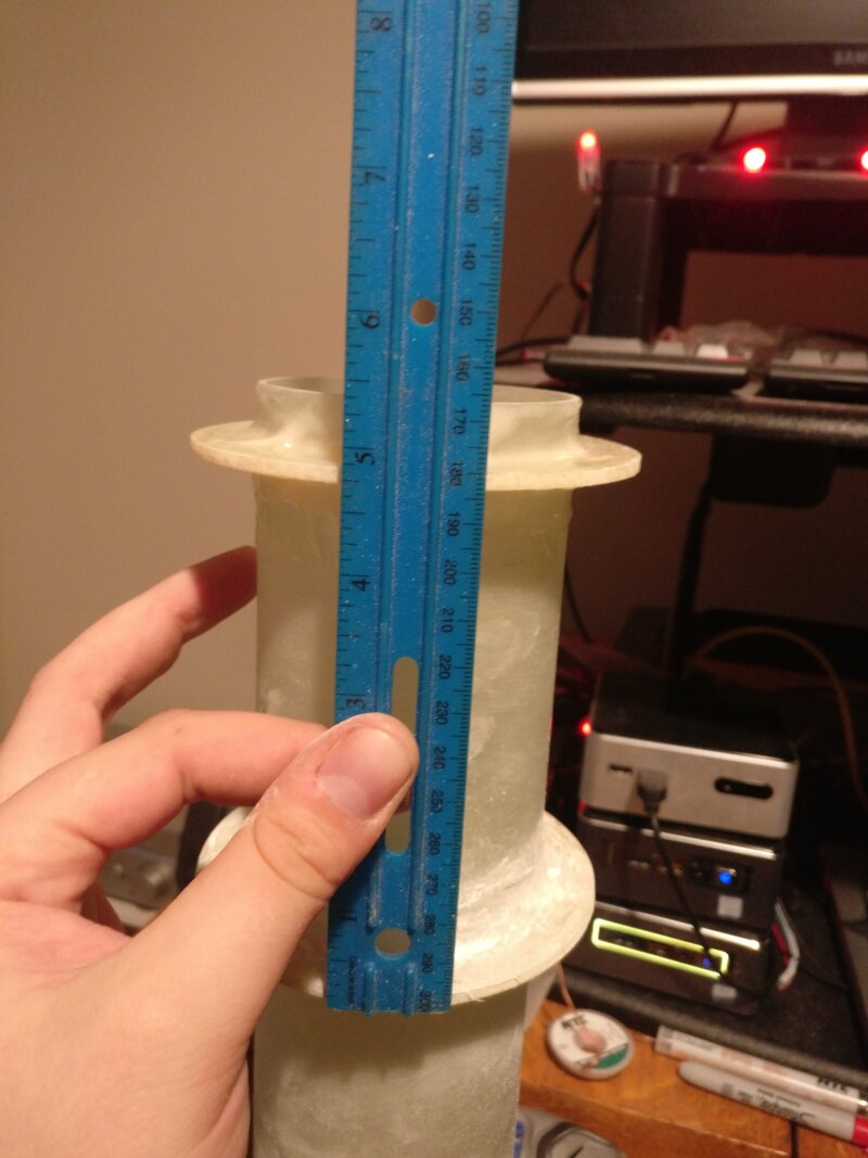
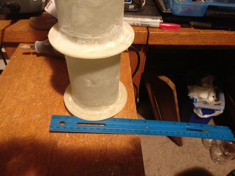
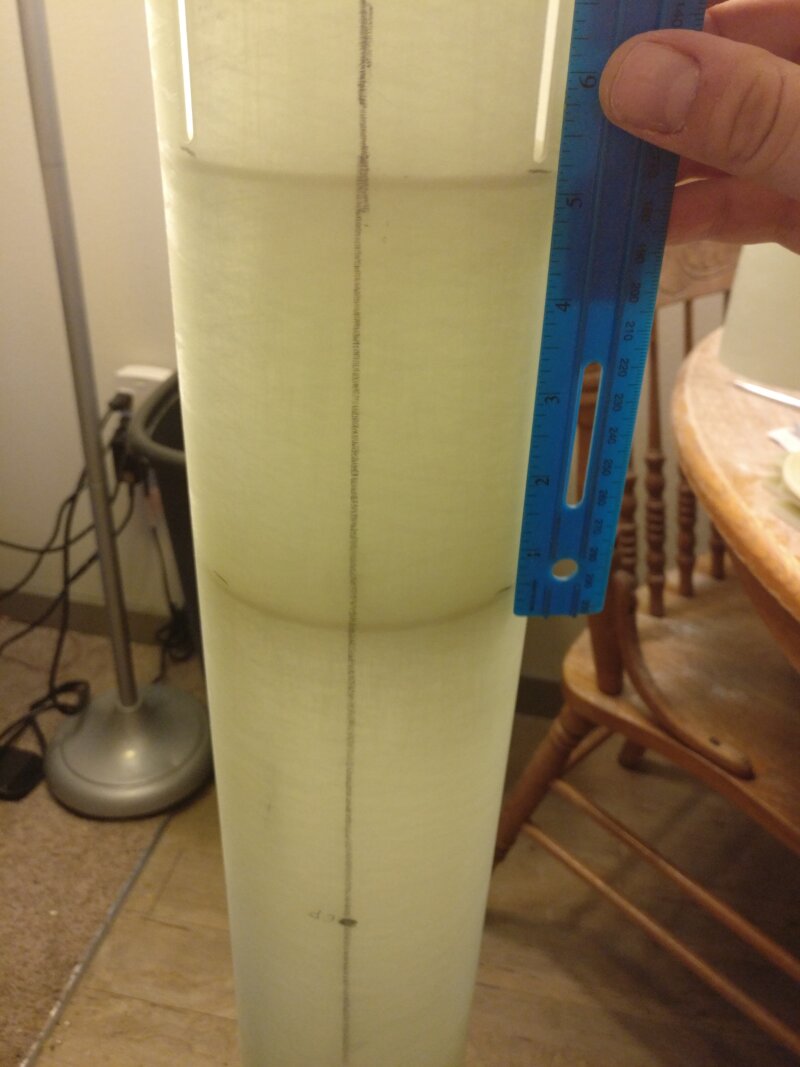
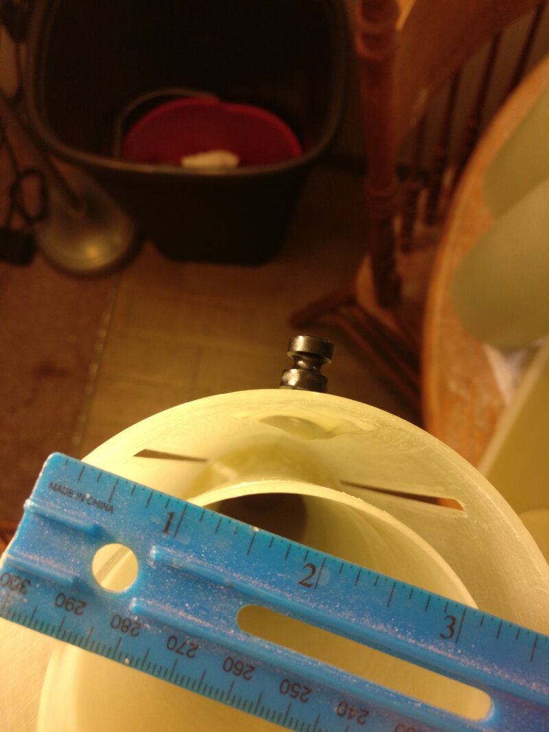
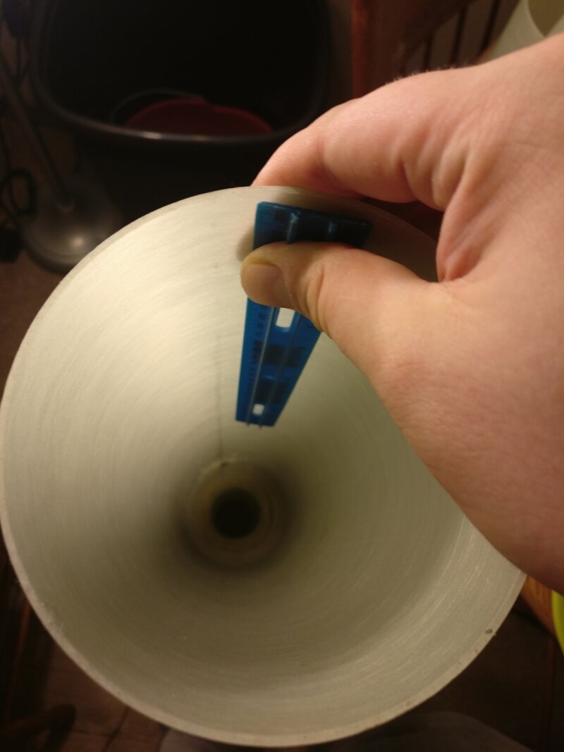
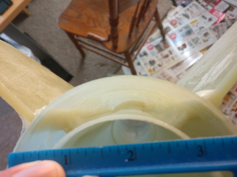
- The middle centering ring was epoxyed 5 1/4” from the same end of the motor tube. (Figures 3 & 4)
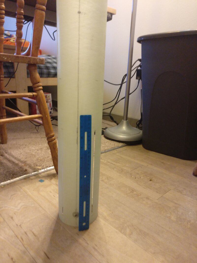
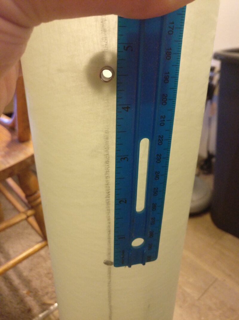
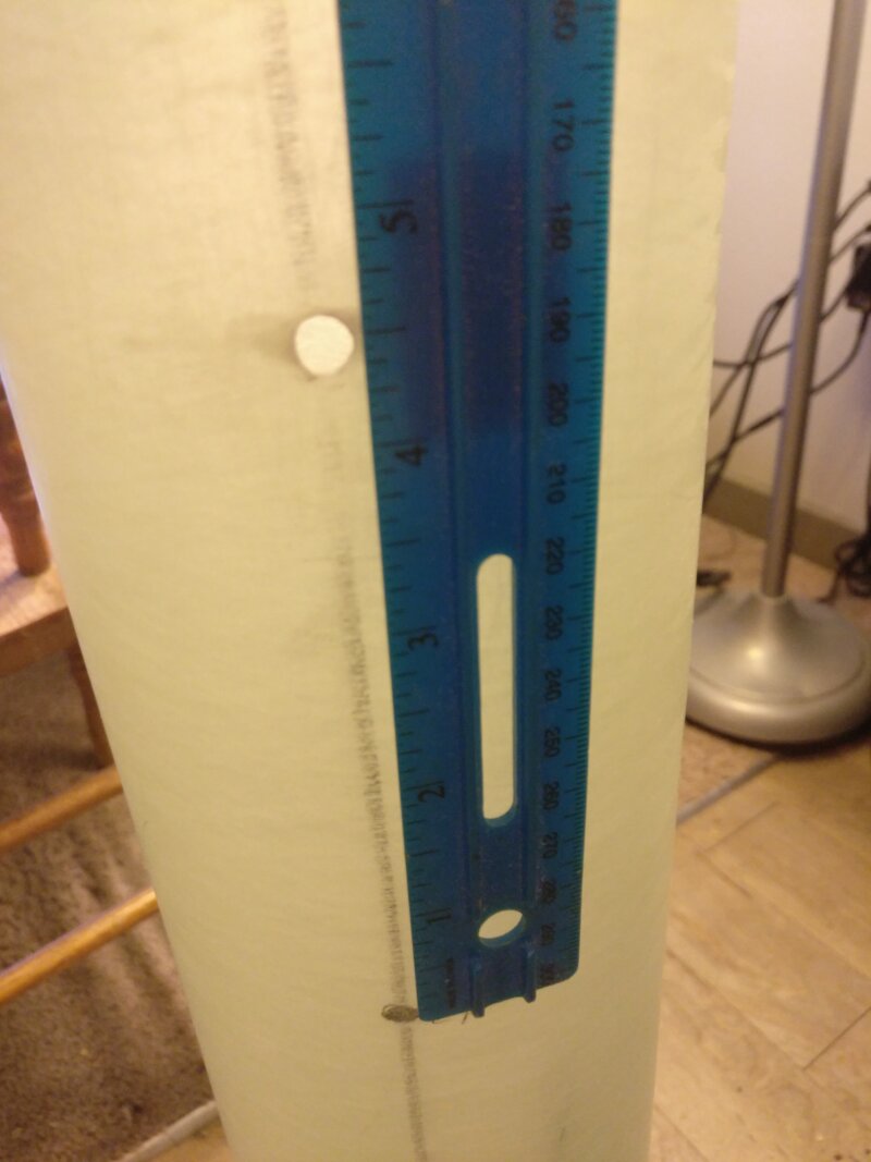
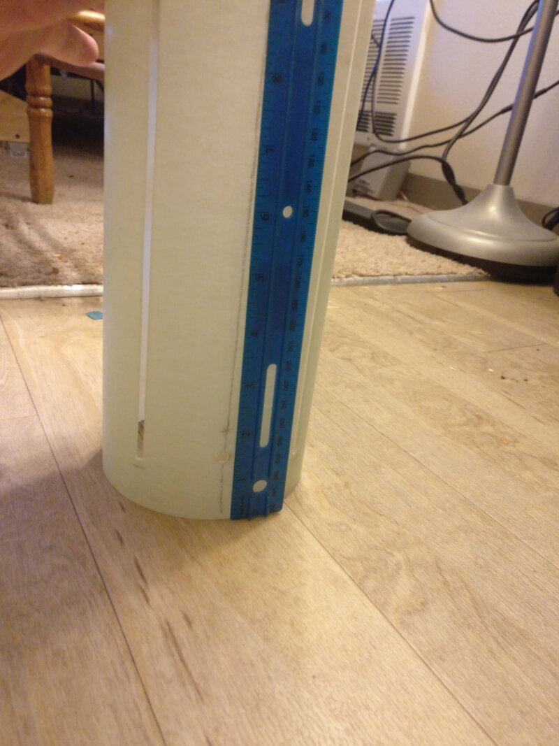
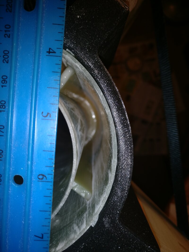
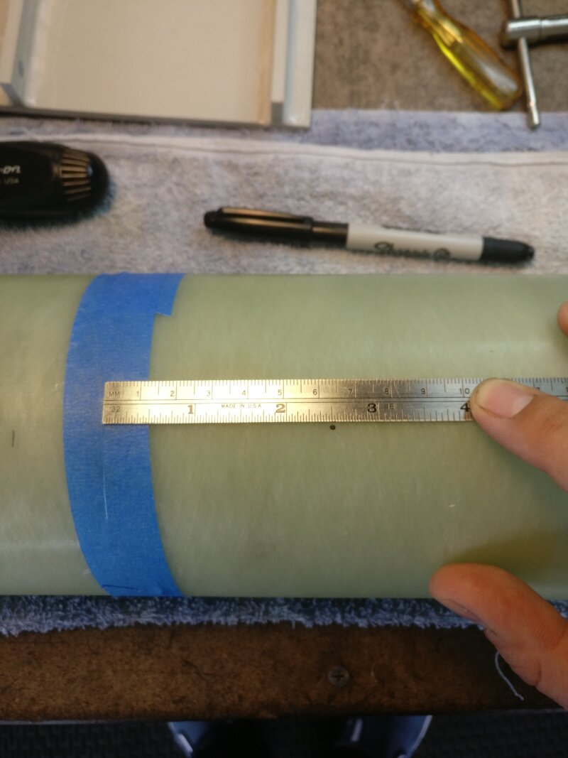
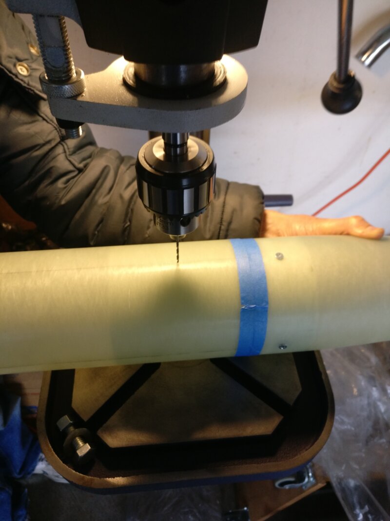
- 1/4” holes were drilled in the airframe for the rail buttons. The aft hole was drilled 1.5” forward of the end of the rocket in order to clear the aft centering ring. The forward hole was drilled 4.5” (1 caliber) ahead of the center of pressure in order to clearly indicate the aftmost center of gravity location for stablilty. (Figures 5-9)
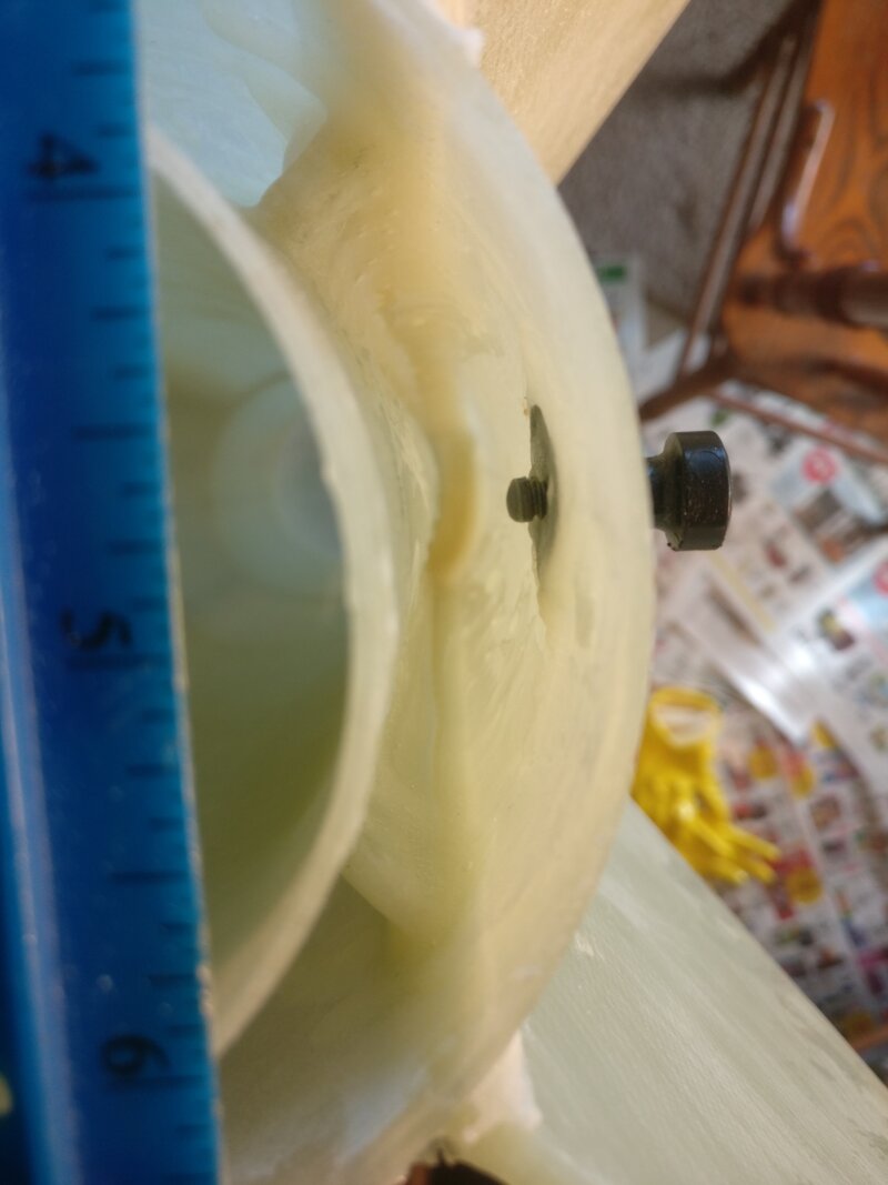
- The T-nuts for the rail buttons were slightly bent to conform to the curvature of the airframe and were epoxyed in place. The rail buttons were drilled out with a 1/4” drill bit so they would fit over the protruding portion of the T-nuts.
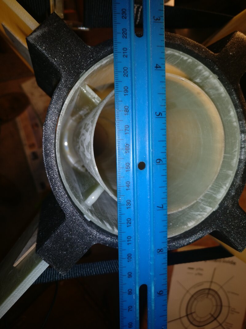
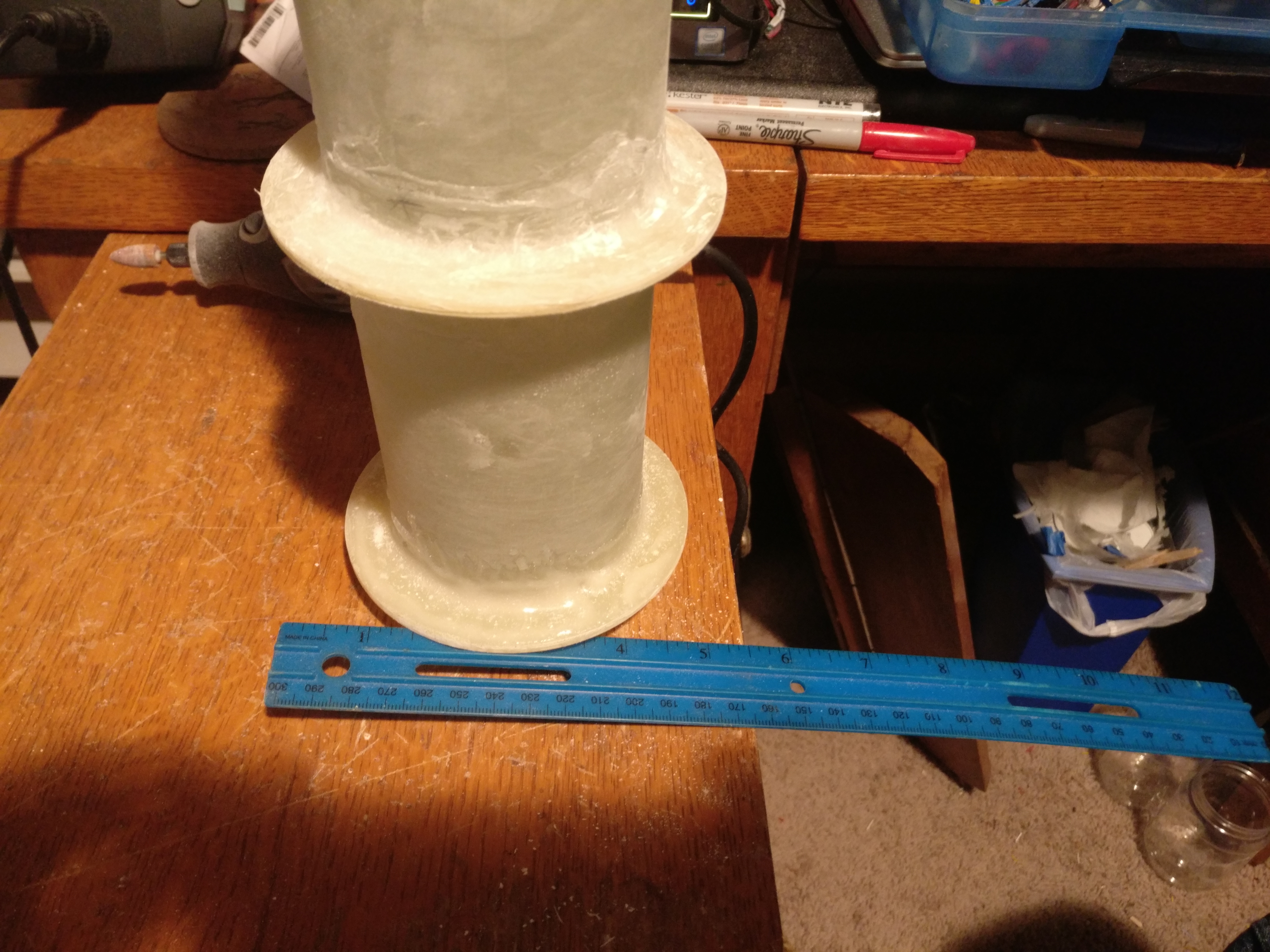
- The motor mount was test-fitted and secured in place with epoxy. The mid centering ring was aligned with the forward edge of the fin slots. (Figures 10-13)
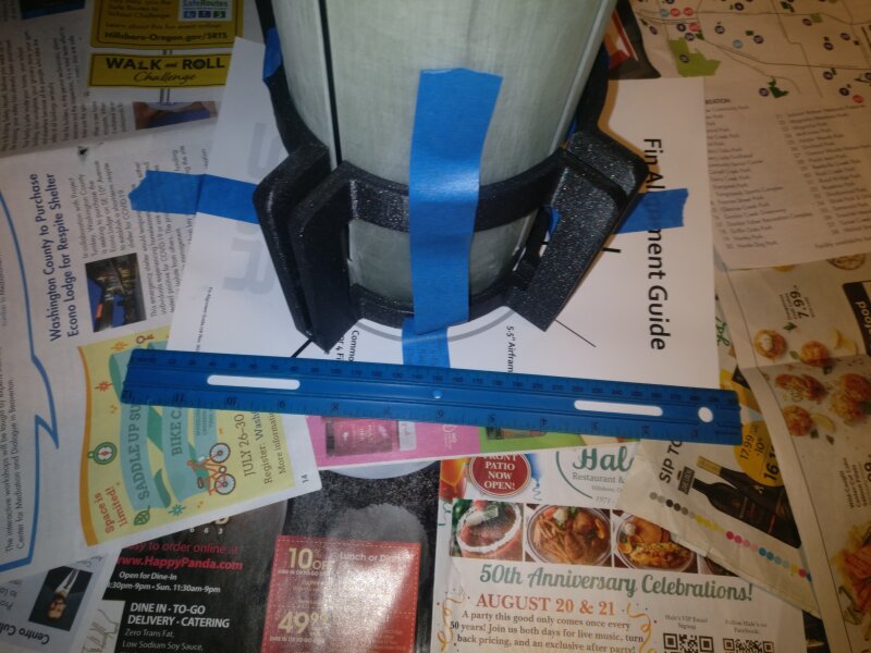
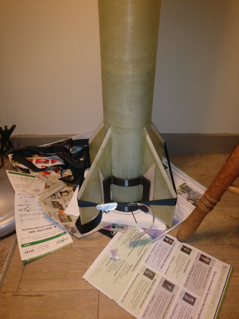
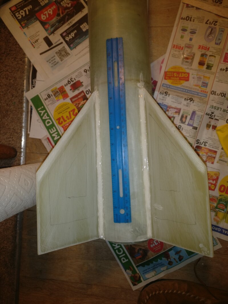
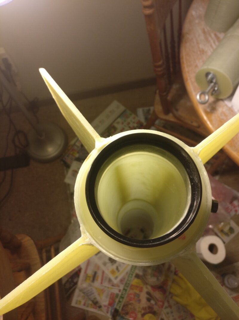
- The 3-D printed plastic fin guide was aligned with the fin slots and taped down to prevent it moving. Scott Binder’s paper fin alignment guide (shipped with any HPR rocket he sells) was used for visual verification that the fins were straight. (Figure 14)
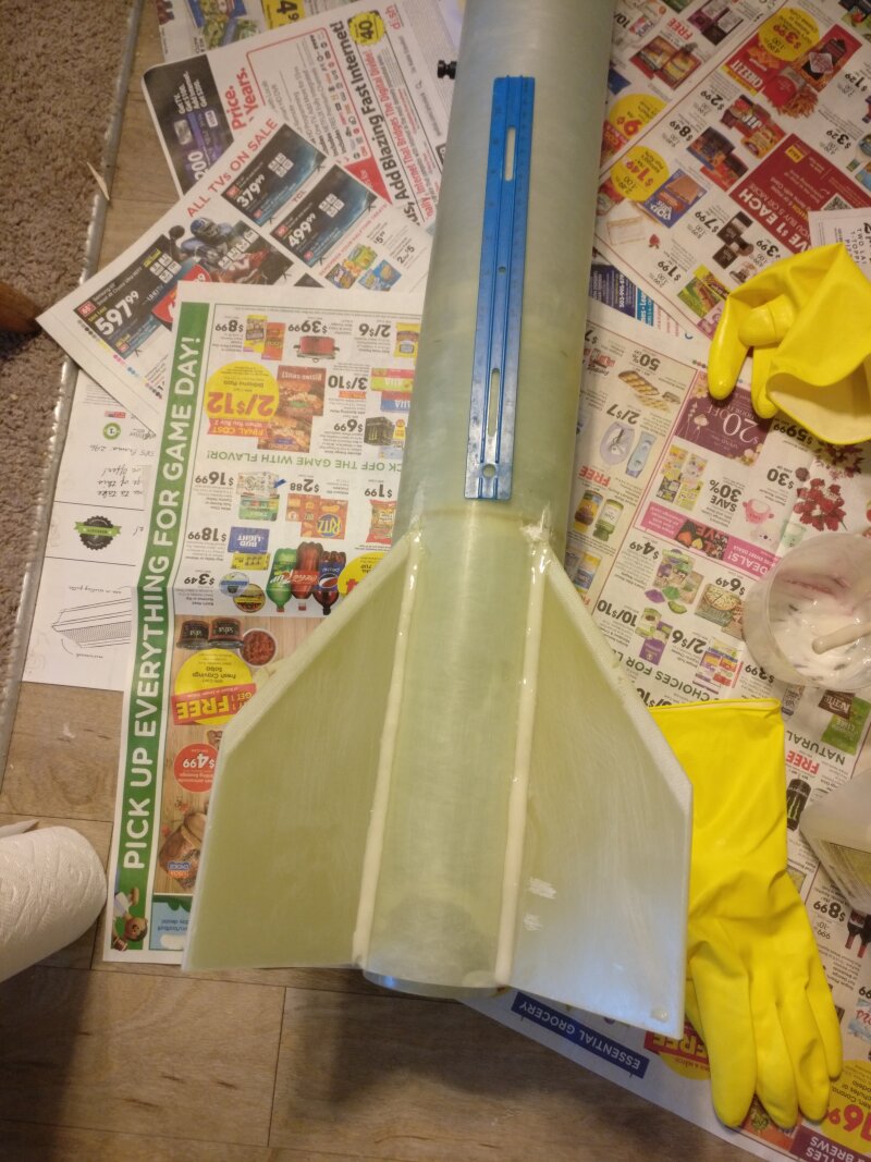
- Epoxy was applied to the root edge of each fin and the fin was inserted into the slot until it firmly contacted the motor tube. Thin balsa sheets were inserted between the fin and the plastic fin guide to center the fins. Once all 4 fins were in place, a nylon strap was wrapped around them and gently tightened. The fins came out very straight! (Figures 15-17)
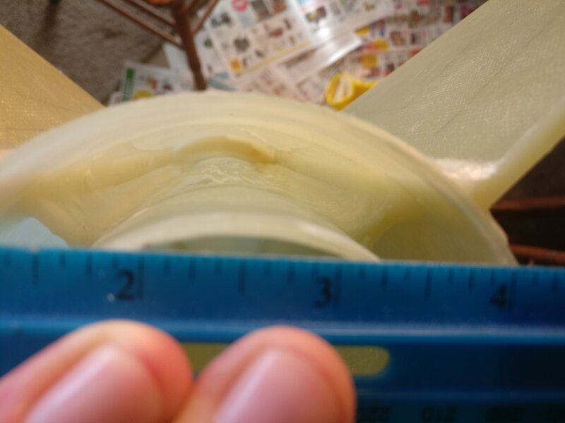
- West System 105/205 epoxy was mixed with 406 colloidal silica until it reached a consistency of peanut butter. It was applied with a long dowel between one of the fins and the airframe to make an internal fillet. As seen in Figure 18, it did not go well and this approach was abandoned.
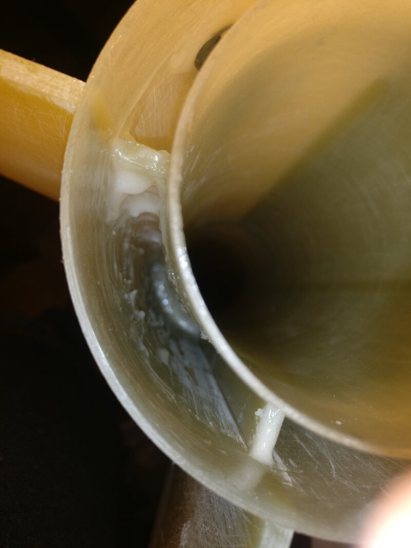
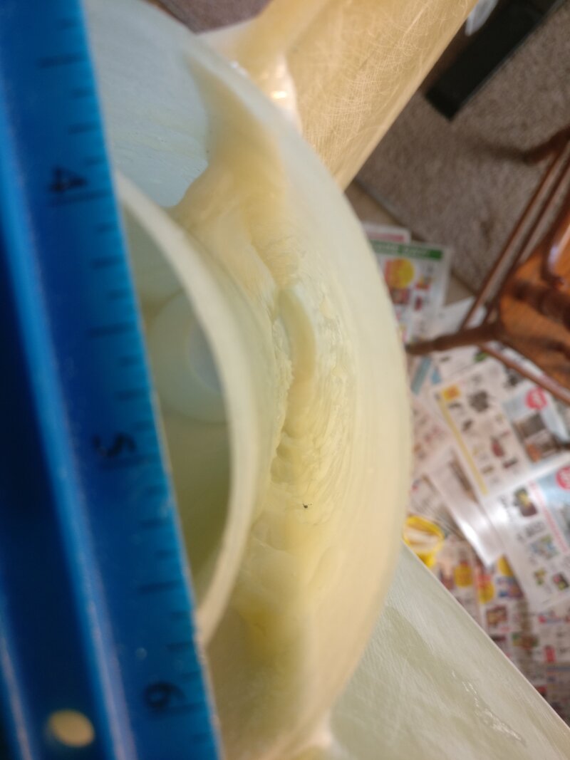
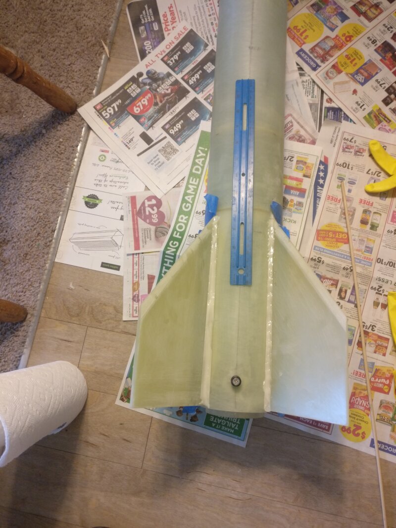
- Internal fillets were formed by this method: two pumps of West System 105/205 resin/hardner were mixed and thickened with 406 colloidal silica to a consistency of honey. It was loaded into a syringe and applied between the fin and the airframe (or motor tube). The airframe was tilted forward down until the epoxy ran down the length of the joint and touched the middle centering ring. This was repeated, 4 at a time, for a total of 16 internal fillets. (Figures 19-22)
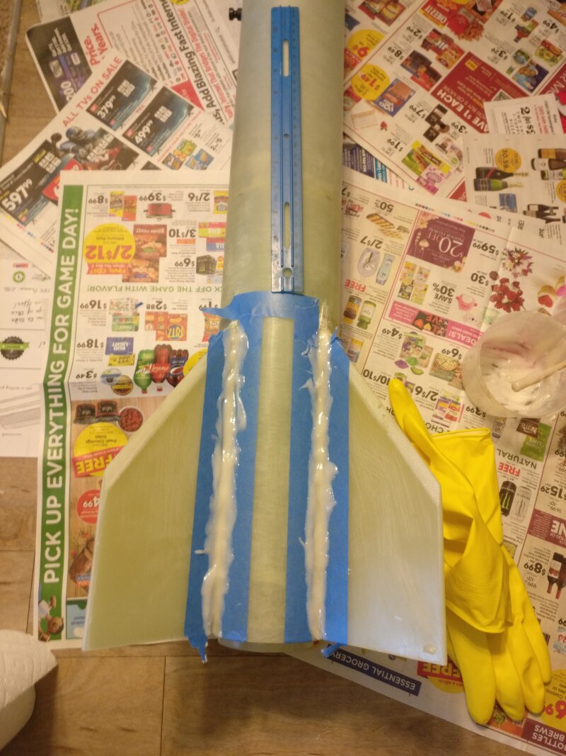
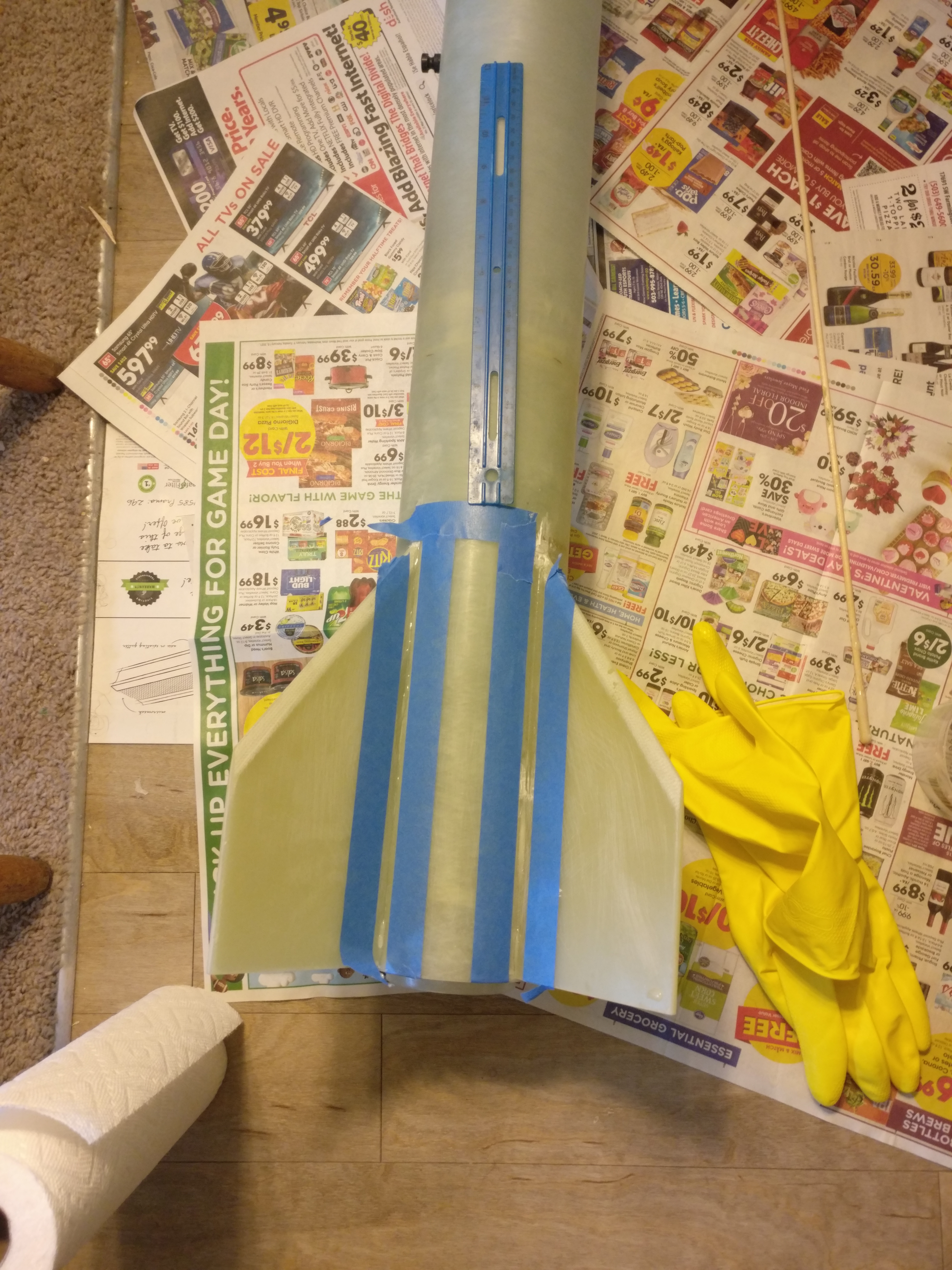
- External fillets were made. Tape was laid out on the fins and airframe to form where the epoxy would go (Figure 23). Next, epoxy was mixed with colloidal silica to a consistency of mayonnaise and applied to the joint between the airframe and fins (Figure 24). The epoxy was smoothed out with a gloved finger dipped in isopropyl alcohol and the tape was removed to make nice smooth fillets (Figures 25-26).
- The tip-to-tip fiberglassing of the fins was performed.
- The fins, external fillets, and airframe were sanded with 80 grit sandpaper to give the epoxy something to stick to. The dust was removed with a wet paper towel.
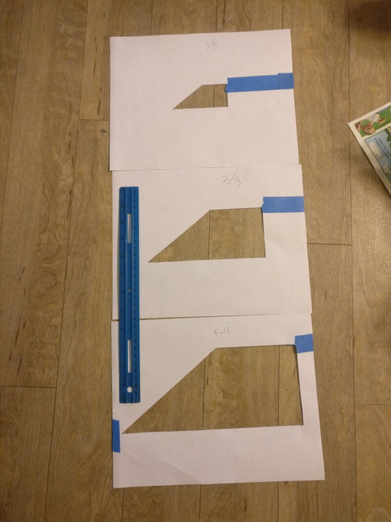
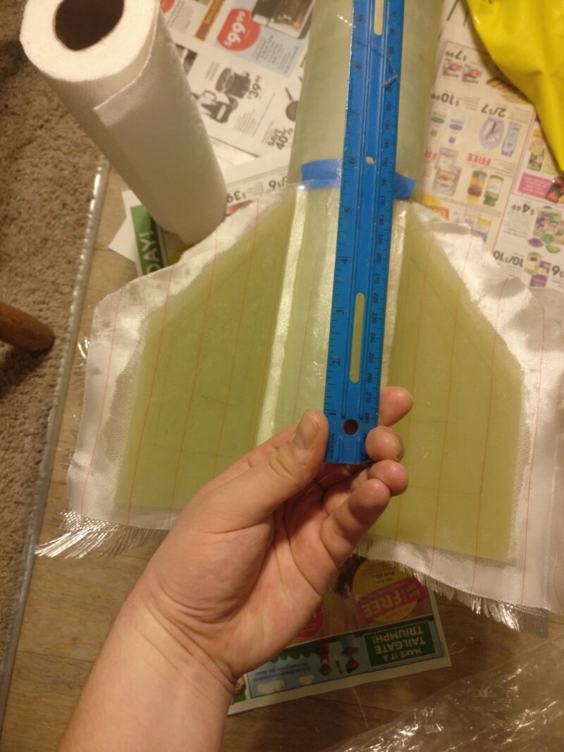
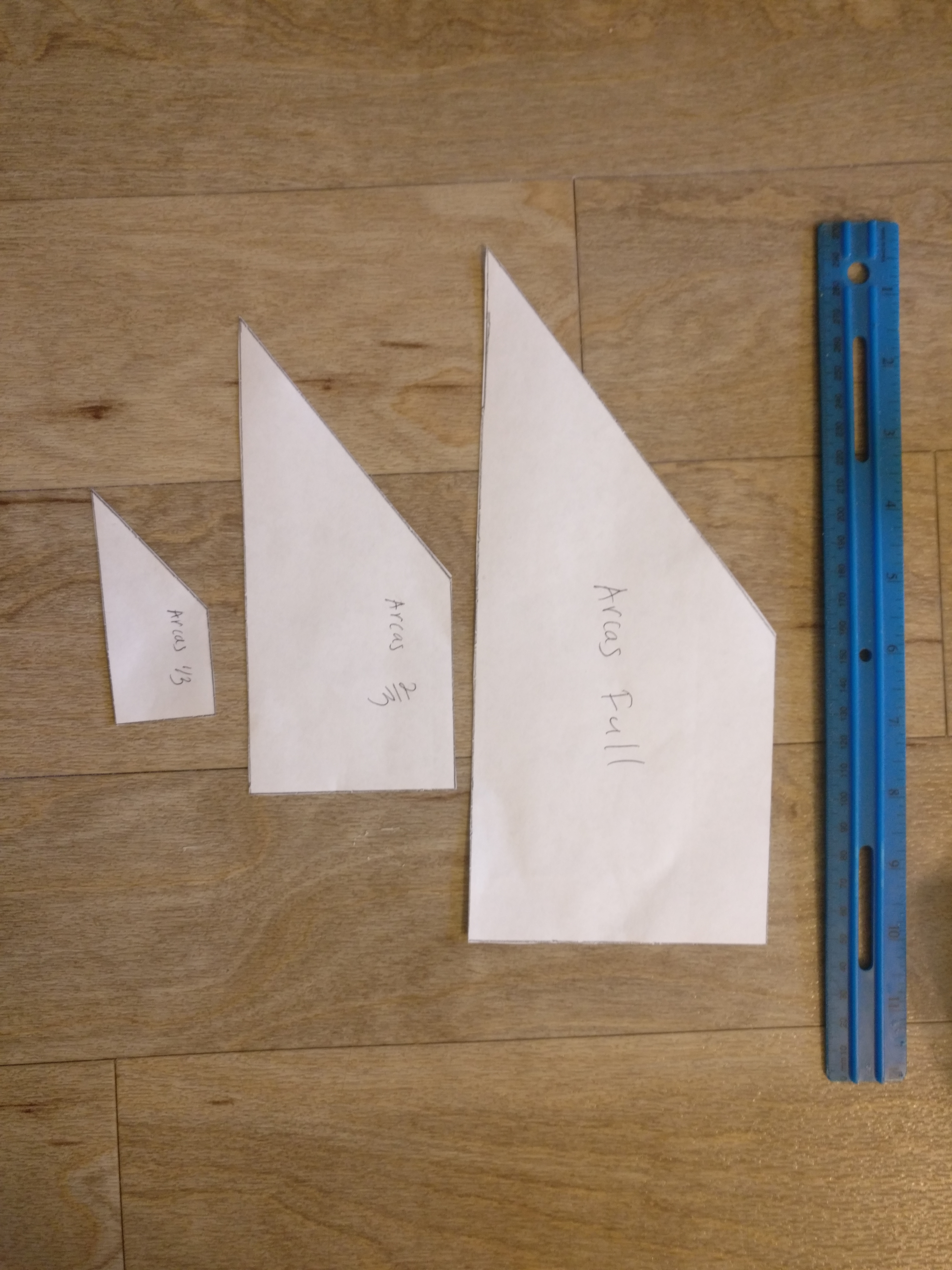
- Templates of the fins (1/3, 2/3, and full scale) were cut out (Figures 27 and 31). The outer templates were taped back together with masking tape.
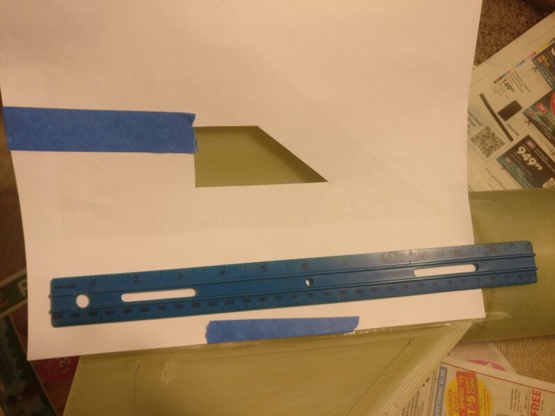
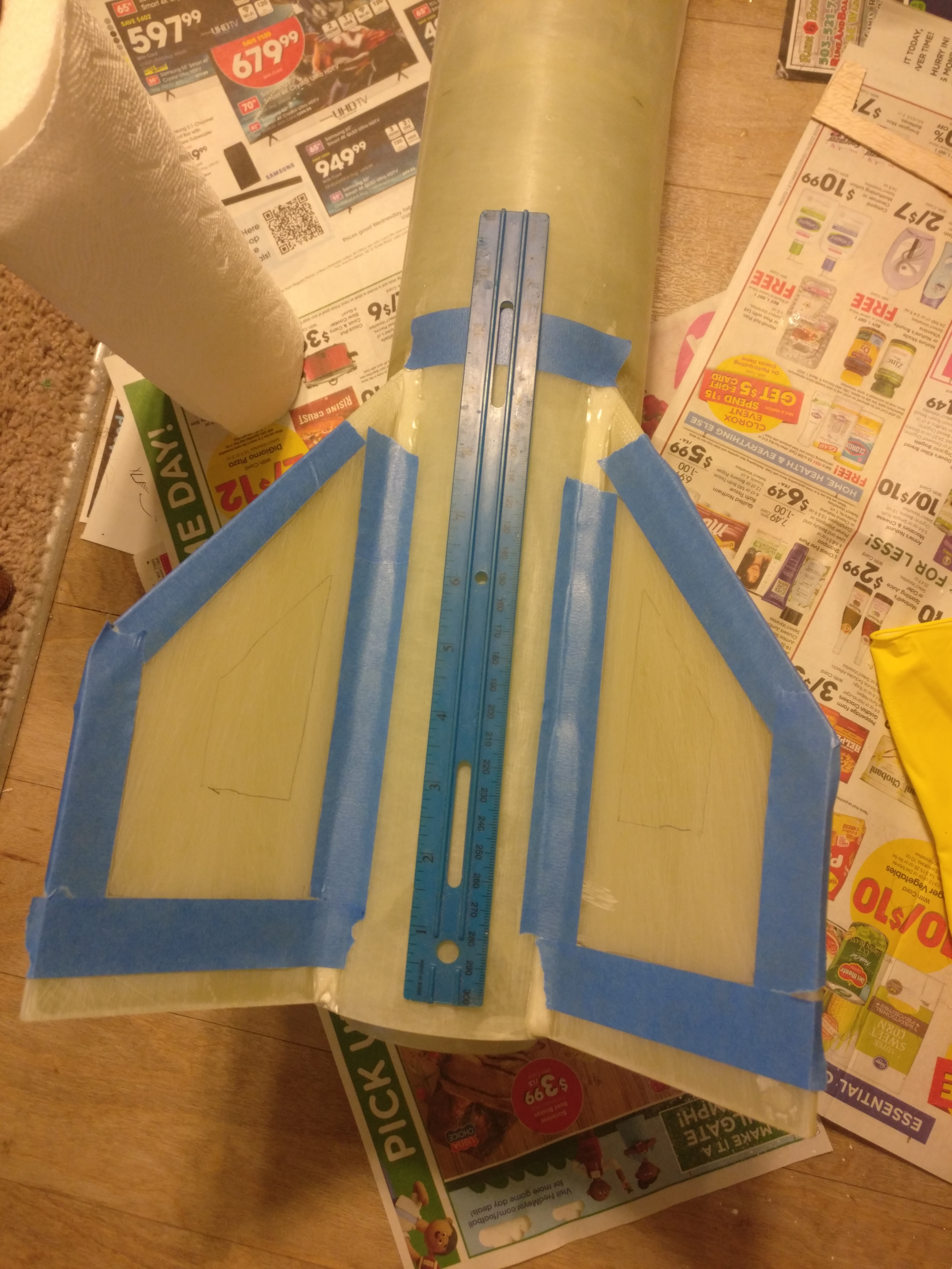
- The outer templates were used to mark on the fins where the fiberglass would go (Figures 28 and 29). Masking tape was placed around the borders of where the 2/3 size fiberglass would go (Figure 30). This step was found to be unnecessary and was not repeated for the other fins.
- Using a rolling cutter and the inner templates (Figure 31), fiberglass cloth was cut out in 1/3, 2/3, and full tip-to-tip sizes. Peel ply was cut to span across the two fins.
- Two pumps resin/hardner of West System 105/207 epoxy were mixed with no filler added. The 207 hardner has a longer pot life and dries clear.
- Epoxy was applied to the fins and airframe between the fins. The 1/3 fiberglass piece was placed down on each fin and epoxy was applied with a 1” paint brush until it was just barely wet. Same for the 2/3 and full tip-to-tip pieces.
- Peel ply was placed on top of the fins and the airframe and wetted with epoxy. (Figure 32)
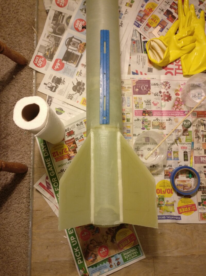
- The epoxy was allowed to cure for 4 hours. Then the peel ply was removed and the excess fiberglass cloth trimmed with a sharp hobby knife. The epoxy cured overnight and then the edges of the fins were lightly sanded with 80 grit sandpaper to remove any stray strands of fiberglass. The end result is shown in Figure 33.
- 1/8” vent holes were drilled in the booster and upper airframe to allow for pressure equalization during a rapid climb.
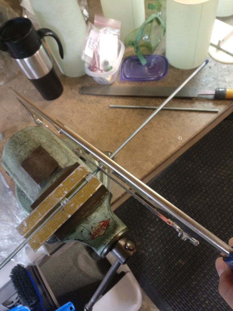
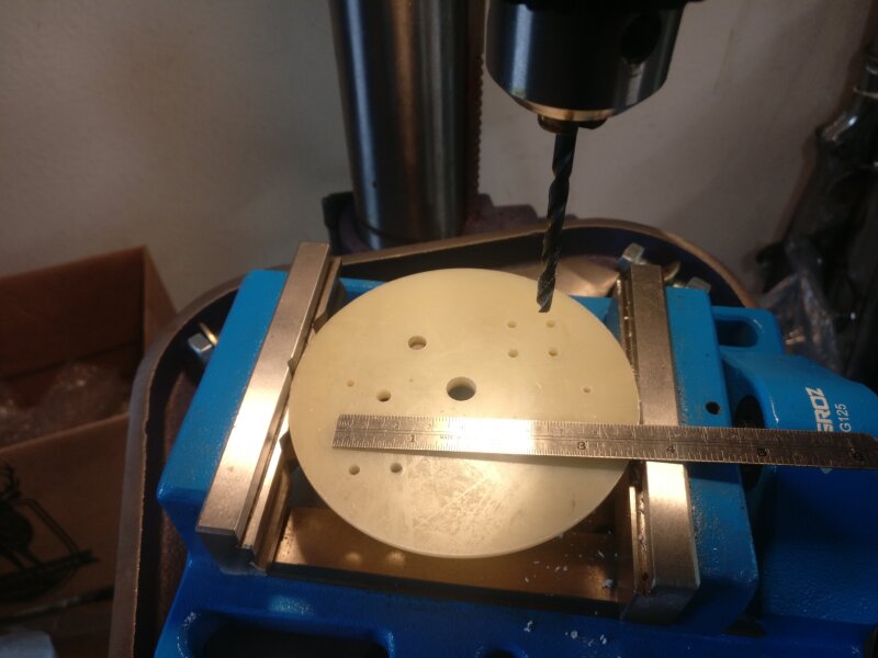
- Construction of the e-bay was started. 1/4” holes were drilled in the bulkheads for the allthreads (Figure 34). The allthreads were cut to size (Figure 35).
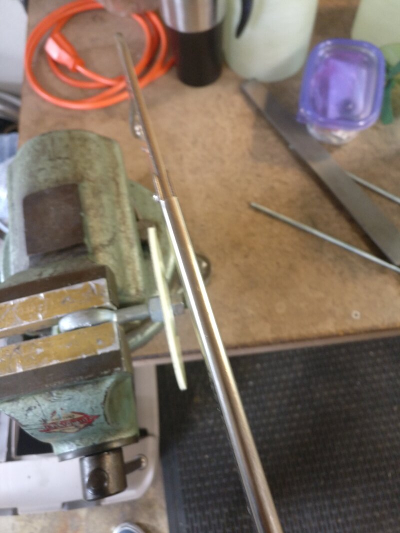
- The eyebolt for the nosecone was installed on the bulkplate. Loctite (permenant) was used on the threads to keep them from coming loose. The excess length was then removed (Figure 36). The nosecone bulkplate was epoxyed to the nosecone coupler with the eyebolt facing inward (Figure 37).
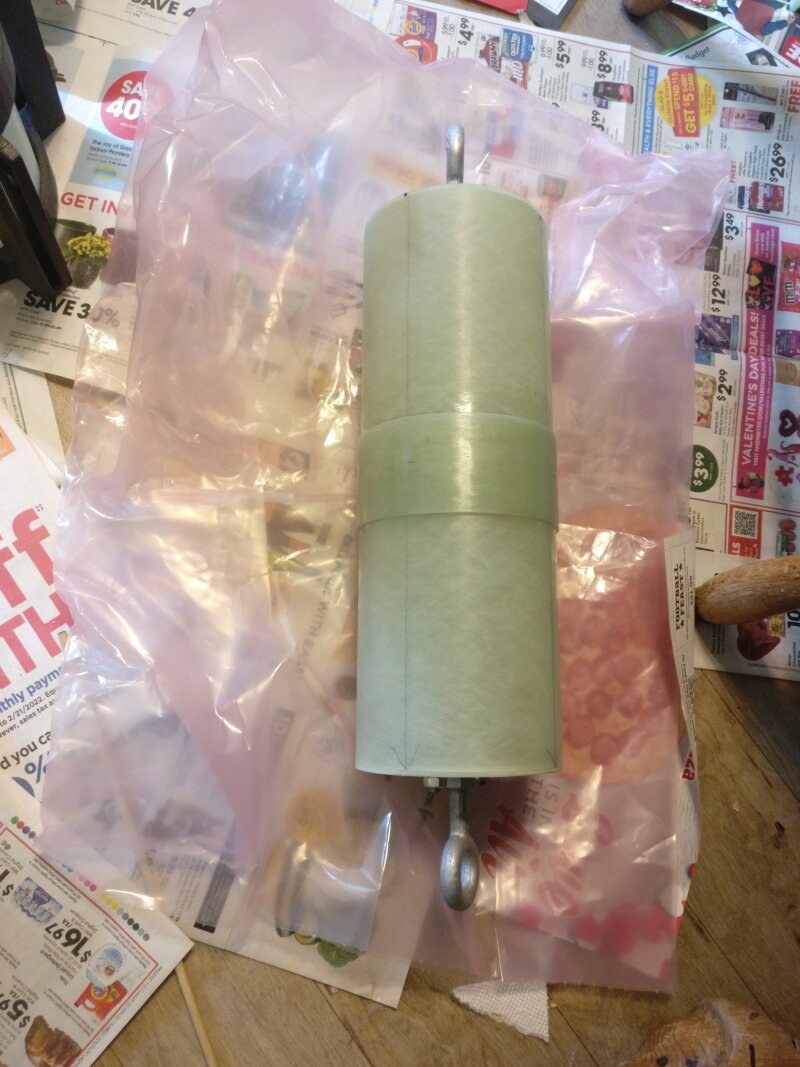
- The switchband was epoxyed to the e-bay coupler (Figure 38).
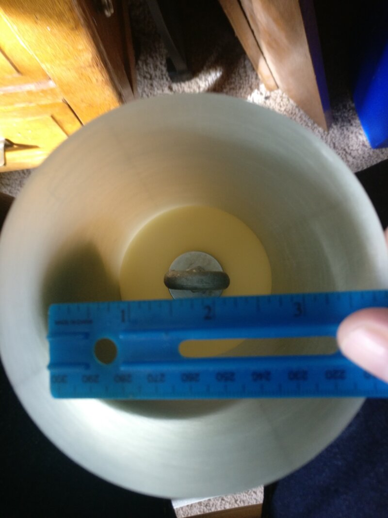
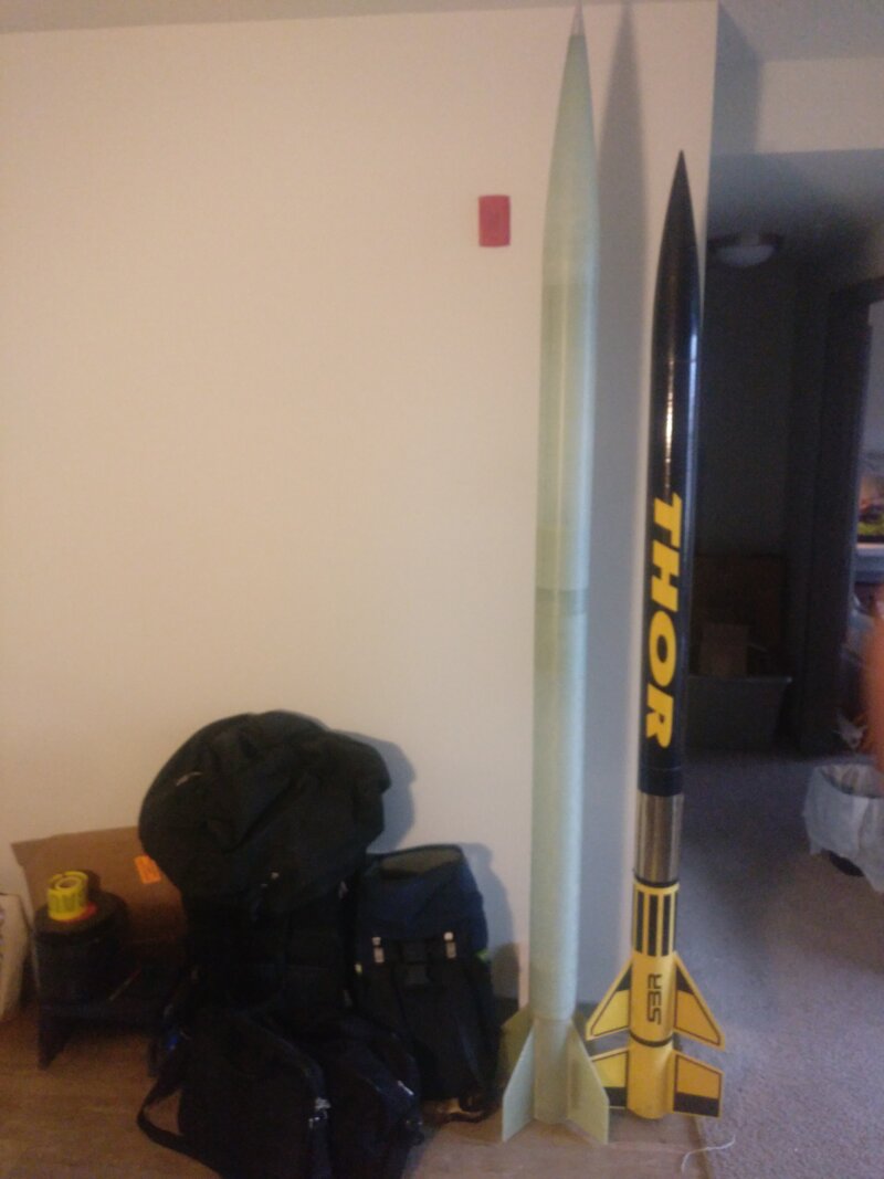
- The aft centering ring was epoxyed in place with West System 105/207, and the AeroPack motor retainer was attached with J-B Weld (Figure 39). At this point, the full rocket was able to be assembled (Figure 40; 4” SBR Thor shown for size comparison).
- Holes for the 4-40 shear pins were marked and drilled with a #43 drill bit (Figures 41 and 42). The holes were tapped for threads, and then the inner holes were widened with a #30 drill bit to prevent the sheared off pins from getting stuck.
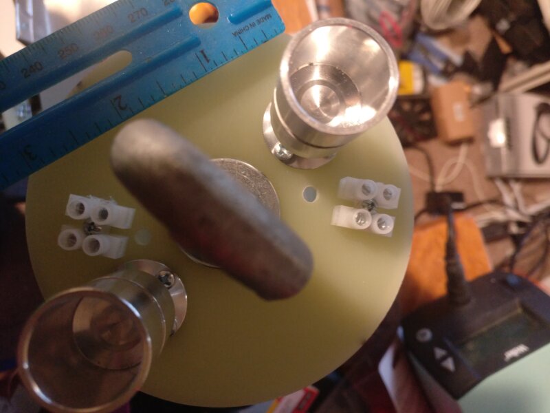
- Holes were drilled to mount the charge wells (9/64”), terminal blocks (7/64”), and wires (3/16”). See Figure 43. The charge wells and terminal blocks were mounted (Figure 44).
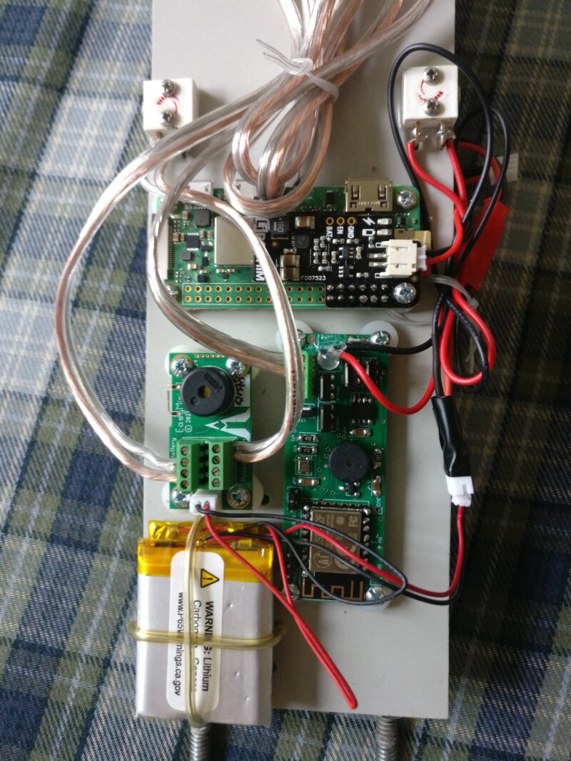
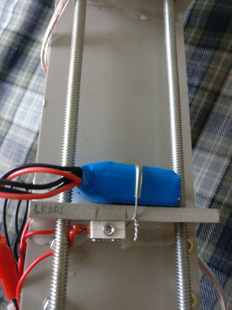
- The electronics and batteries were mounted to the e-bay sled (Figures 45 and 46). All electronics were mounted with stand-offs to prevent the parts on the bottom of the boards from being crushed. The batteries were mounted with safety wire threaded through a plastic tube to prevent the wire from cutting into the batteries. The switches were epoxyed in place because there were no screws long enough to go all the way through the sled.
- After the switches were mounted, 3 1/8” vent/switch access holes were drilled in the switchband. One hole was for the raspberry pi’s switch, one for the primary altimeter (EasyMini), and one for the backup altimeter (EggTimer Quantum). The size and number of holes was guided by the user manual of the EggTimer Quantum. Due to slight error in placing the holes, they were filed into an oblong shape in order to allow the hex key to reach the switches.
Internal Diagram
Construction Photos
The following images document the construction of the Arcas. Each image is numbered to correspond with the Figure number referenced above.
-
 02-fwd-centering-ring
 -
 03-fwd-mid-centering-rings
 -
 04-fwd-mid-centering-rings
 -
 05-rb-t-nut
 -
 06-rb-t-nut
 -
 07-rb-t-nut
 -
 08-rb-hole-upper
 -
 09-rb-hole-lower
 -
 10-motor-tube-test-fit
 -
 11-motor-tube-test-fit
 -
 12-motor-mount-install
 -
 13-motor-mount-install
 -
 14-fin-alignment-guide
 -
 15-fins-installed
 -
 16-fins-installed
 -
 17-fins-drying
 -
 18-fillet-trouble
 -
 19-internal-fillet-1
 -
 20-internal-fillet-2
 -
 21-internal-fillet-3
 -
 22-internal-fillet-4
 -
 23-external-fillet-prep
 -
 24-external-fillet-epoxy
 -
 25-external-fillet
 -
 26-external-fillet
 -
 27-templates
 -
 28-marking
 -
 29-marked
 -
 30-taped
 -
 31-templates
 -
 32-tip-to-tip-fiberglass-peel-ply
 -
 33-tip-to-tip-fiberglass
 -
 34_allthreads_holes
 -
 35_cutting_allthreads
 -
 36_trimming_nosecone_eyebolt
 -
 37_nosecone_eyebolt
 -
 38_ebay_switchband_epoxy
 -
 39_aft_centering_ring_aeropack
 -
 40_arcas_thor
 -
 41_shear_pin_mark
 -
 42_shear_pin_holes
 -
 43_bulkhead_swiss_cheese
 -
 44_bulkhead_complete
 -
 45_electronics_mounted
 -
 46_battery_switch


Recovery Systems
As required for safety and the L3 certification process, the Arcas is equipped with redundant dual-deploy flight computers.
Deployment Sequence
- Motor burnout occurs.
- The EasyMini fires the primary drogue charge at apogee.
- The rocket separates at the booster section and a 50’ long, 10” wide red/metallic silver streamer is deployed.
- Two (2) seconds after apogee, the EggTimer Quantum fires the backup drogue charge.
- The rocket falls at around 70fps under drogue until it reaches 1000ft.
- The EasyMini fires the primary main charge at 1000ft.
- The rocket separates at the nose cone and the main parachute is deployed.
- At an altitude of 800ft, the EggTimer Quantum fires the backup main charge.
- The rocket falls at a descent rate of about 15fps until landing.
Riser Connections
All shock cords are attached to the rocket by 3/8” quick links attached to 3/8” eyebolts.
Shock cord connections:
- Forward closure of the motor (drogue).
- Aft end of the e-bay (drogue).
- Forward end of the e-bay (main).
- Nose cone (main).
Parachute Compartments and Closures
The drogue is housed in the booster section of the rocket, between the motor casing and the e-bay. The main is housed in the forward payload section between the e-bay and nose cone. 4-40 shear pins are used to attach the booster to the e-bay and the nose cone to the forward payload bay. To protect against hot ejection charge gasses, the drogue comes in a nomex/kevlar wrap and will be further wrapped in a nomex blanket with the shock cord. The main will be in a deployment bag, and the corresponding shock cord will be wrapped in a nomex blanket.
Compartment Venting
- Both the booster and the forward payload section have 1/8” vent holes to prevent premature separation.
- The e-bay has 3 1/8” vent holes that also double as switch holes. They are elongated due to minor placement error. The size and number of holes was determined by the recommendation of the EggTimer Quantum manual.
- The nose cone bulkhead has a 1/8” vent hole into the forward payload section.
Descent Rate
On the test flight (K1275R), a 9’ RocketMan parachute was used. The descent rate was recorded by the EasyMini as 28fps. While the rocket was not damaged, this is too fast. A bigger parachute is not an option, since there is not much room in the forward payload bay, so a more efficient one will be used instead.
An 8’ RocketMan High Efficiency (coefficient of drag is 2.2 instead of 0.9) will be used. Per the manufacturer, it is rated 29.8lbs at 15fps. The rocket will weigh 23lbs after motor burnout, so there is some margin of error. The rocket should descend around 15fps.
Recovery Component Description
Control Devices
- Primary: Altus Metrum EasyMini
- Determines altitude with barometric pressure sensor.
- Powered by a 1S LIPO battery.
- Armed/Safed by a FingerTech 40A Mini Power Switch. A hex key is inserted through the vent hole on the switchband to actuate the switch. The switch is connected to the “switch” terminals of the EasyMini.
- The EasyMini is mounted with through-hole screws, washers, and nuts. Spacers are used to prevent components on the bottom from being crushed, and to make the USB port accessible.
- Backup: EggTimer Quantum
- Determines altitude with barometric pressure sensor.
- Powered by a 2S LIPO battery.
- Same switch configuration used, except it’s wired in series with the positive battery terminal.
- Same mounting method.
Electronics Schematic
Parachutes
- Main: 8’ RocketMan High Performance Parachute (coefficient of drag: 2.2). Red/White.
- Drogue: 50’ long 10” wide RocketMan Extreme Streamer. Red/Silver (reflective)
- Parachute bags:
- Main: Rocketman 4”x8” Kevlar/NOMEX bag with integrated pilot chute.
- Drogue: built-in Kevlar/NOMEX pouch that wraps around the streamer.
Risers
- 3/4” wide 2500lbs strength nylon
- Both sections are 25’ long
- Secured to 3/8” quick links with “quadruple” knots.
Mounting Hardware
- All mounting points are 3/8” forged eyebolts.
- 3/8” quick links connect shock cord to eyebolts.
Pyrotechnic Devices
- Total of 4: Primary Drogue, Backup Drogue, Primary Main, Backup Main
- Electric matches are used to ignite the black powder charges.
- Drogue charges are 3g black powder (each).
- Main charges are 2.5g black powder (each).
- The above amounts were determined by this calculator plus about 1/2 gram extra. Experience has shown that these calculators tend to be conservative.
Screenshots of calculations:
Recovery Device Testing
Both the EasyMini and the EggTimer Quantum were extensively tested prior to use on the Arcas.
- Both flight computers were test-flown on an SBR Horizon.
- After installation on the Arcas, both flight computers were checked to see that they had no continuity (no shorts) with no igniters connected, and correct continuity with igniters connected (no BP for safety). This test revealed a single-strand short in one of the connections. It will be repeated before launch.
- A ground test was performed using the EggTimer Quantum to verify that the shear pins would be cut, the rocket would separate, and the drogue / main would be ejected.
- Another ground test will be performed prior to the L3 Cert flight since both the drogue and main parachutes are being changed.
Stability
Launch Pad
The launch pad should have a stable base and a 10’ 1515 rail.
Center of Pressure
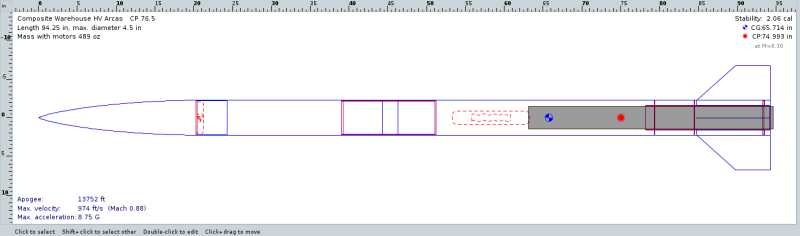
The center of pressure was calculated by OpenRocket to be at 74.9 inches from the tip of the nose cone. It is permanently marked on the rocket. See below for the OpenRocket file, and see the above diagram.
Aft CG Limit
70.4in from the nose cone
Estimated CG
65.7in from the nose cone (OpenRocket)
Flight Profile
The below data was obtained from the OpenRocket Simulation.
- Launch Weight: 30.3lbs
- Motor: M650W (5964Ns total impulse)
- Thrust-to-weight ratio: 10.9
- Estimated Drag Coefficient: 0.54408
- Off-Rail Velocity: 73.9fps
- Rail buttons clear the rail at 0.286 seconds into the flight.
- Minimum Aerodynamic Stability Velocity: 43.85fps (reached at 43.8in on the rail)
- Maximum Expected Velocity: 974fps
- Maximum Expected Altitude: 13,752ft
- Maximum Expected Acceleration: 8.78G
Pre-Launch Checklist
- Gather Required Equipment
- Rocketry toolkit
- Hex wrench for electronics
- wrenches for e-bay
- yellow-handle slotted screwdriver
- orange screwdriver
- electrical tape
- High-power box
- Black powder
- >= 8 e-matches
- >= 16 4-40 shear pins
- Recovery wadding
- Table / Chair
- Arcas
- M650W (pre-loaded into RMS 75/6400; I hate loading motors in the wind)
- Rocketry toolkit
- Safety
- Igniter continuity checks will be performed before black powder is present.
- After coordinating with the OROC mailing list, the transmit frequency of the EggFinder is: 913Mhz ID 3
- Motor installation
- Remove AeroPack Retainer. Thread swivel, quick link, and shock cord through motor mount tube.
- Attach quick link to 3/8” forged eyebolt installed into forward closure of motor.
- Stuff shock cord (and hardware) back into motor tube and insert motor.
- Replace AeroPack Retainer ring.
- Electronics Preparation
- Verify no black powder present in charge wells and no e-matches connected.
- All batteries to be fully charged before the launch.
- Inspect electronics for damage. Close e-bay, tighten nuts, and power on both flight computers.
- Check that no continuity is present on any of the four (4) channels. This is a check for shorts. Power off electronics.
- Trim igniter leads and connect to terminal blocks.
- With no BP present, power on electronics and check all four (4) channels for positive continuity.
- POWER OFF ELECTRONICS!!!
- Pyrotechnics Preparation
- Verify that both flight computers are powered off.
- Unscrew all 4 charge wells.
- Screw a charge well to the locking nut and put on scale. Tare scale.
- Using funnel, measure BP into charge wells. 2.5G for each Main charge and 3.0g for each Drogue charge.
- Screw charge well into base on the bulkhead and insert corresponding ignitor.
- Pack 3 squares of recovery wadding into charge well. Completely cover charge well with electrical tape so no BP can escape.
- Recovery System
- Inspect drogue, main parachute, parachute bag, fire blankets, and both shock cords for damage. Replace any damaged components.
- Untangle shroud lines and shock cords.
- Connect forward shock cord quick links to nose cone and fwd end of e-bay. Connect main parachute to loop in shock cord.
- Connect aft shock cord quick links to aft end of e-bay and motor forward closure. Connect drogue streamer to loop in shock cord.
- Roll up streamer and wrap in accompanying kevlar bag. Coil up aft shock cord and put in fire blanket with streamer. Load into airframe.
- Attach top of main parachute to parachute bag with tether. Pack parachute and shroud lines into parachute bag. Coil up fwd shock cord and wrap in fire blanket. Load into aiframe.
- Place aft end of e-bay coupler into booster and install 4 shear pins.
- Do not install nose cone yet, as the EggFinder GPS still needs to be loaded.
- Final assembly
- Verify that both EasyMini and Eggtimer Quantum are powered off.
- Power on and install EggFinder GPS module into 54mm tube. Remove the 4 screws that hold the nosecone onto its coupler, insert the tube with the GPS into the nose cone, and replace and tighten the screws. Place the nose cone onto the fwd payload bay and insert 4 shear pins.
- Verify that igniter is taped to the side of the rocket.
- Verify CG is at least 4.5” (one airframe diameter) forward of CP (marked on rocket). The fwd rail button is convieniently placed 4.5” forward of the CP to aid in this test.
- Verify that rail buttons are aligned.
- Launch Checklist
- Equipment
- Arcas
- Extra masking tape
- Hex wrench for arming electronics
- Eggfinder receiver LCD module
- Phone with OSMAnd map app
- Water!
- Fill out flight card and get RSO approval.
- Take rocket to away cell when the range is open.
- Power on Raspberry PI once at the pad. It is the switch opposite the flight computer switches. DO NOT power on flight computers.
- Lower rail and place rocket onto the rail. Move rocket into launching position and lock rail.
- Verify launch angle is away from the spectator area.
- Arm EasyMini and wait for 3 beeps to indicate full igniter continuity.
- Power on EggFinder Quantum. Wait a few minutes until it beeps continuously.
- Install igniter and secure with masking tape.
- Connect leads to igniter.
- Arm the launch control box (if last one to leave away cell).
- Verify witnesses are ready.
- Hand flight card to LCO and let them know electronics are burning on the pad!
- Equipment
- Post-flight checklist
- Celebrate that the rocket was found in the sage!
- Visually inspect all 4 charge wells. If unfired charges are present, remove the igniters.
- Power off both flight computers.
- SSH to Raspberry PI with phone. Stop the video recording and gracefully shut it down. Use hex wrench to disconnect the battery.
- Inspect rocket for damage. Verify (expensive!) motor casing is present.
- Haul the rocket back to the flightline and pour Jim some fine whiskey.
- Contingency Checklist
- Misfire
- After waiting at least 60 seconds, approach the rocket and disarm the launch control box.
- Replace igniter.
- Audibly verify that both altimeters are still armed.
- Re-arm the launch control box.
- Launch abort
- Approach the rocket and disarm the launch control box.
- Remove igniter and tape to side of rocket.
- Use hex wrench to disarm both flight computers.
- Power off Raspberry PI with hex wrench.
- Remove rocket from pad.
- Crash
- Bring fire extinguisher and shovel!
- If the e-bay somehow survived, disarm flight computers with hex wrench. If unable to access switches, remove all unfired igniters.
- Swear profusely, as the rocket is probably completely destroyed. :-(
- Battery Life
- Abort if the rocket has been on the pad more than 2 hours.
- Misfire
Flight and Results
The Arcas was flown on May 13 2022 on an M650W to an altitude of about 13,000’ AGL. The rocket weathercocked slightly off the pad but the flight was otherwise straight. Both drogue and main parachutes deployed when they were supposed to, and the rocket was spotted decending on the main chute. The rocket was recovered just off the access road close to the launch site. No damage was observed and the flight was deemed successful.